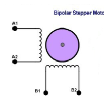
Bipolar Stepper Motor
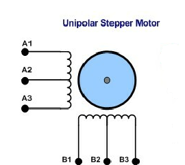
Unipolar Stepper Motor
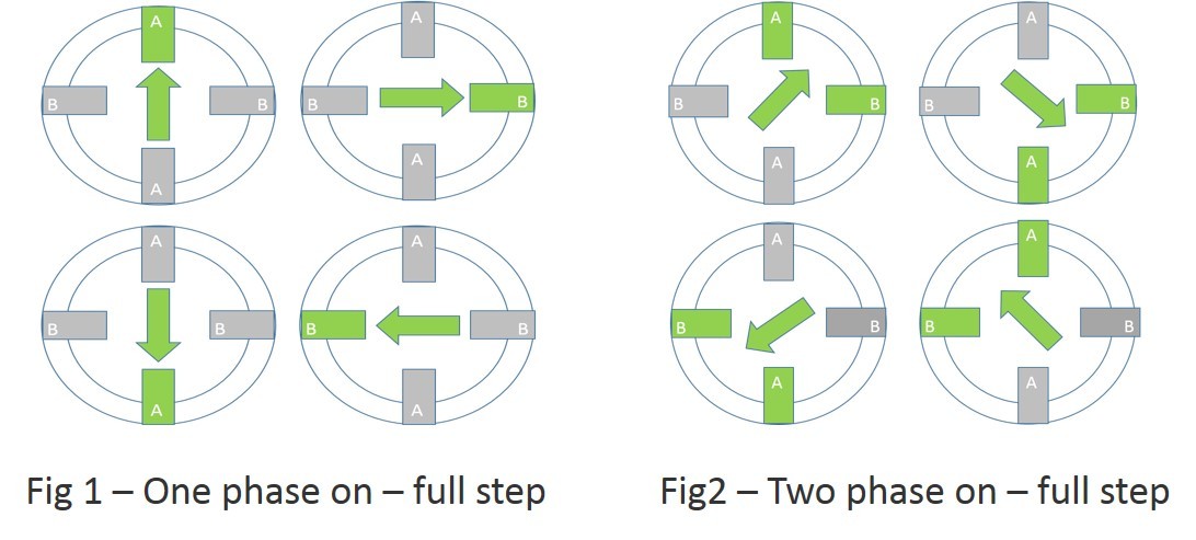
Full Step
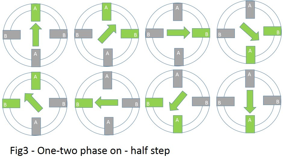
Half Step
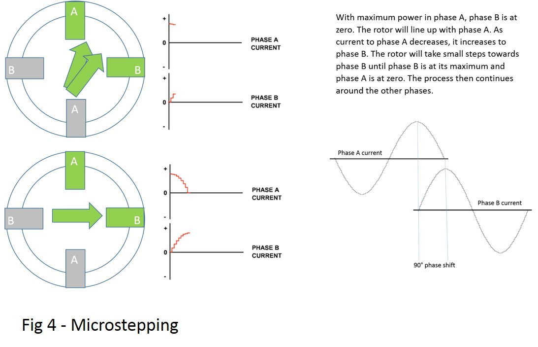
Micro Step
Calculating the Steps per Revolution for Stepper Motor
Need of Driver modules for Stepper motors
/*  Name     : main.c
 *  Purpose  : Source code for Full Step Drive Unipolar Stepper Motor
               Interfacing with Arduino.
 *  Author   : Gemicates
 *  Date     : 08-02-2018
 *  Website  : www.gemicates.org
 *  Revision : None
 */

#include <Stepper.h> //include the function library

// set pin numbers:

// Pins 1, 2, 3, 4 connected to stepper motor through L293D

const int a1 = 1;

const int a2 =  2;

const int b1 =  3;

const int b2 =  4;

void setup() {

// initialize the digital pins as an output

pinMode(a1, OUTPUT);

pinMode(a2, OUTPUT);

pinMode(b1, OUTPUT);

pinMode(b2, OUTPUT);

// set the pins LOW by making the voltage level LOW

digitalWrite(a1, LOW);

digitalWrite(a2, LOW);

digitalWrite(b1, LOW);

digitalWrite(b2, LOW);

}

void loop(){

step1();

delay(200);

step2();

delay(200);

step3();

delay(200);

step4();

delay(200);

}

void step1 (){

digitalWrite(a1, HIGH);

digitalWrite(a2, HIGH);

digitalWrite(b1, LOW);

digitalWrite(b2, LOW);

}

void step2 (){

digitalWrite(a1, LOW);

digitalWrite(a2, HIGH);

digitalWrite(b1, HIGH);

digitalWrite(b2, LOW);

}

void step3 ()

{

digitalWrite(a1, HIGH);

digitalWrite(a2, LOW);

digitalWrite(b1, LOW);

digitalWrite(b2, HIGH);

}

void step4 (){

digitalWrite(a1, LOW);

digitalWrite(a2, LOW);

digitalWrite(b1, HIGH);

digitalWrite(b2, HIGH);

}
/*  Name     : main.c
 *  Purpose  : Source code for Half Drive Unipolar Stepper Motor
               Interfacing with Arduino.
 *  Author   : Gemicates
 *  Date     : 08-02-2018
 *  Website  : www.gemicates.org
 *  Revision : None
 */

#include <Stepper.h> //include the function library

// set pin numbers:

// Pins 1, 2, 3, 4 connected to stepper motor through L293D

const int a1 = 1;

const int a2 =  2;

const int b1 =  3;

const int b2 =  4;

void setup() {

// initialize the digital pins as an output

pinMode(a1, OUTPUT);

pinMode(a2, OUTPUT);

pinMode(b1, OUTPUT);

pinMode(b2, OUTPUT);

// set the pins LOW by making the voltage level LOW

digitalWrite(a1, LOW);

digitalWrite(a2, LOW);

digitalWrite(b1, LOW);

digitalWrite(b2, LOW);

}

void loop(){

step1();

delay(60);

step2();

delay(60);

step3();

delay(60);

step4();

delay(60);

step5();

delay(60);

step6();

delay(60);

step7();

delay(60);

step8();

delay(60);

}

void step1 (){

digitalWrite(a1, HIGH);

digitalWrite(a2, LOW);

digitalWrite(b1, LOW);

digitalWrite(b2, HIGH);

}

void step2 (){

digitalWrite(a1, HIGH);

digitalWrite(a2, LOW);

digitalWrite(b1, LOW);

digitalWrite(b2, LOW);

}

void step3 ()

{

digitalWrite(a1, HIGH);

digitalWrite(a2, HIGH);

digitalWrite(b1, LOW);

digitalWrite(b2, LOW);

}

void step4 (){

digitalWrite(a1, LOW);

digitalWrite(a2, HIGH);

digitalWrite(b1, LOW);

digitalWrite(b2, LOW);

}

void step5 (){

digitalWrite(a1, LOW);

digitalWrite(a2, HIGH);

digitalWrite(b1, HIGH);

digitalWrite(b2, LOW);

}

void step6 (){

digitalWrite(a1, LOW);

digitalWrite(a2, LOW);

digitalWrite(b1, HIGH);

digitalWrite(b2, LOW);

}

void step7 (){

digitalWrite(a1, LOW);

digitalWrite(a2, LOW);

digitalWrite(b1, HIGH);

digitalWrite(b2, HIGH);

}

void step8 (){

digitalWrite(a1, LOW);

digitalWrite(a2, LOW);

digitalWrite(b1, LOW);

digitalWrite(b2, HIGH);

}
/*  Name     : main.c
 *  Purpose  : Source code for Wave Drive Unipolar Stepper Motor
               Interfacing with Arduino.
 *  Author   : Gemicates
 *  Date     : 08-02-2018
 *  Website  : www.gemicates.org
 *  Revision : None
 */

#include <Stepper.h> //include the function library

// set pin numbers:

// Pins 1, 2, 3, 4 connected to stepper motor through L293D

const int a1 = 1;

const int a2 =  2;

const int b1 =  3;

const int b2 =  4;

void setup() {

// initialize the digital pins as an output

pinMode(a1, OUTPUT);

pinMode(a2, OUTPUT);

pinMode(b1, OUTPUT);

pinMode(b2, OUTPUT);

// set the pins LOW by making the voltage level LOW

digitalWrite(a1, LOW);

digitalWrite(a2, LOW);

digitalWrite(b1, LOW);

digitalWrite(b2, LOW);

}

void loop(){

step1();

delay(200);

step2();

delay(200);

step3();

delay(200);

step4();

delay(200);

}

void step1 (){

digitalWrite(a1, HIGH);

digitalWrite(a2, LOW);

digitalWrite(b1, LOW);

digitalWrite(b2, LOW);

}

void step2 (){

digitalWrite(a1, LOW);

digitalWrite(a2, LOW);

digitalWrite(b1, HIGH);

digitalWrite(b2, LOW);

}

void step3 ()

{

digitalWrite(a1, LOW);

digitalWrite(a2, HIGH);

digitalWrite(b1, LOW);

digitalWrite(b2, LOW);

}

void step4 (){

digitalWrite(a1, LOW);

digitalWrite(a2, LOW);

digitalWrite(b1, LOW);

digitalWrite(b2, HIGH);

}
/*  Name     : main.c
 *  Purpose  : Source code for Bipolar Stepper Motor
               Interfacing with Arduino.
 *  Author   : Gemicates
 *  Date     : 08-02-2018
 *  Website  : www.gemicates.org
 *  Revision : None
 */

#include <Stepper.h> //include the function library

// set pin numbers:

// Pins 1, 2, 3, 4 connected to stepper motor through L293D

const int a1 = 1;

const int a2 =  2;

const int b1 =  3;

const int b2 =  4;

void setup() {

// initialize the digital pins as an output

pinMode(a1, OUTPUT);

pinMode(a2, OUTPUT);

pinMode(b1, OUTPUT);

pinMode(b2, OUTPUT);

// set the pins LOW by making the voltage level LOW

digitalWrite(a1, LOW);

digitalWrite(a2, LOW);

digitalWrite(b1, LOW);

digitalWrite(b2, LOW);

}

void loop(){

step1();

delay(60);

step2();

delay(60);

step3();

delay(60);

step4();

delay(60);

}

void step1 (){

digitalWrite(a1, LOW);

digitalWrite(a2, LOW);

digitalWrite(b1, LOW);

digitalWrite(b2, HIGH);

}

void step2 (){

digitalWrite(a1, LOW);

digitalWrite(a2, HIGH);

digitalWrite(b1, LOW);

digitalWrite(b2, LOW);

}

void step3 ()

{

digitalWrite(a1, LOW);

digitalWrite(a2, LOW);

digitalWrite(b1, HIGH);

digitalWrite(b2, LOW);

}

void step4 (){

digitalWrite(a1, HIGH);

digitalWrite(a2, LOW);

digitalWrite(b1, LOW);

digitalWrite(b2, LOW);

}